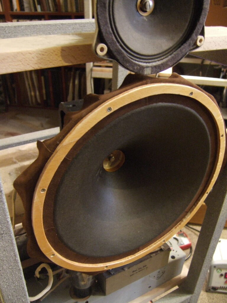
In anticipation of new projects in the field of acoustic systems using field coil (FC) speakers, I began researching who is currently working in this field. It turns out that there are many manufacturers of full-range and compression drivers based on the field coil principle, such as Coherent and Supravox. Additionally, there is an entire industry focused on converting vintage Altec and JBL drivers to field coil technology. This raises the question: is there a rational reason for this, and how can it be done correctly if it is worthwhile?
Some years ago, I wrote a short article (still available on the website) about different types of field coils. However, it turned out to be too superficial and narrowly focused, mainly discussing how to supply power to the coil. Today, I want to revisit these questions and offer new insights.
The Sound Improvement from Field Coils
First, does magnetization with a coil and an external power supply provide a significant improvement in sound compared to a permanent magnet? After years of tinkering with vintage speakers with field coil magnetization, I can confidently say that speakers with field coils sound different. They offer more energy in the sound, which is especially noticeable in the human voice. Our ears are sensitive to the slightest imperfections in voice reproduction, and field coils provide a certain «individual character.» One distinctive feature of a speaker with electrical magnetization is that it responds differently to dynamic nuances, particularly with crescendo and fortissimo. It «holds» these dynamics, creating the feeling that the sound has something to rely on as it gains volume.
While I may not have the advanced physics knowledge to explain the behavior of the magnetic field in the gap with different magnetization methods, I sense that the quality of the magnetic field is different when using a field coil. Many trusted persons have conducted more precise experiments replacing permanent magnets with coils, and they have observed these changes, describing them similarly.
Additionally, it is known that the coloration of sound, a characteristic of any material, is audible even in parts of the audio system where there is no actual signal. By replacing a large piece of aluminum, cobalt, or other alloys with copper in the field coil, you can clearly hear these changes, even though there is no clear scientific explanation. I invite the «smart, scientifically oriented gays» who despise such so-called «esoteric» phenomena to perform a simple experiment: place a heavy copper piece on your output transformers (if you use tube amplifiers, of course) and then a piece of steel. You’ll begin to understand why replacing a permanent magnet with an equal mass of copper can result in significant changes to the subjective perception of sound, even if we exclude the effects on the magnetic field properties. Many home stereo systems, especially those built by purely technical enthusiasts, often lack musicality or transparency, which may lead scientifically minded gays stick to their opinions. .
Flexibility and Adjustability of FC Speakers
Second, the field coil speaker is highly flexible in terms of adjustments. The quality factor (Q ) of the speaker’s moving system can be changed by altering the supply voltage to the coil. Today, in a world dominated by numbers, many believe that a higher magnetic field induction in the gap leads to better sound. However, this is not true!
In my experiments with field coil speakers, I have consistently found that there is a limit beyond which an overdamped loudspeaker begins to sound much worse. Flexibility and fluidity are lost, the bass becomes ragged and dry, and voice reproduction becomes hysterical . This can be partly explained by the saturation of the core material and partly by the overtones introduced by a more rigid moving system. It’s similar to the phenomenon that occurs when an amplifier overdamps a speaker, and then a small series resistor (1-2 ohms) can notecable improve sound quality.
In this sense, the sound of a compression driver or a typical paper speaker with a permanent magnet is determined by the factory’s magnetization parameters. Meanwhile, I always keep in mind that a slight decrease in the magnetic induction in the gap (compared to the maximum possible value) can make the sound more flexible, relaxed, with full-bodied bass.
Wide Range of Tuning with FC Speakers
Third, an FC speaker can change its voice over a wide range, depending on the used wires, power cords, types of rectifiers, and capacitors used in the power supply unit. This allows the speaker to be adapted to your needs and your equipment, giving the sound the desired coloration and characteristics. A speaker with a permanent magnet simply cannot offer this opportunity.
Disadvantages and Challenges
However, field coil speakers come with their own disadvantages and difficulties:
- The Field Coil Itself Does Not Guarantee Good Sound
The loudspeaker is a complex system, and the magnetic field in the gap is just one factor. Many old field coil speakers sound terrible and must be in museums. In some cases, a well-designed permanent magnet speaker will sound cleaner, more musical, and just more pleasant to ear than its field coil counterpart. This is often due to better overall design, a better cone, and a more finely tuned / balanced system. You cannot evaluate a speaker solely based on the fact that it has a field coil. - The Importance of the Power Supply
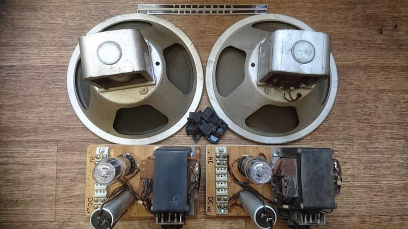
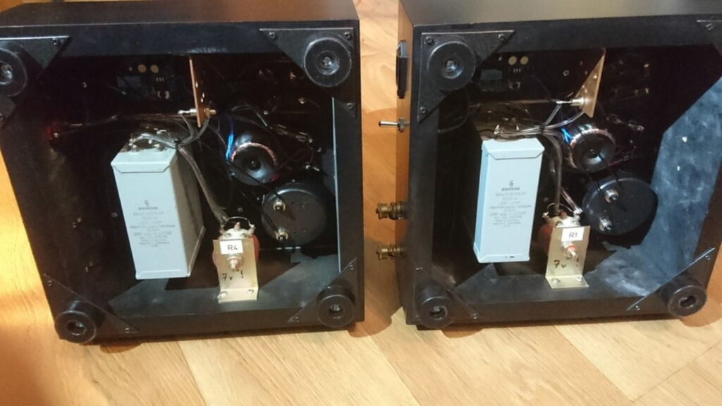
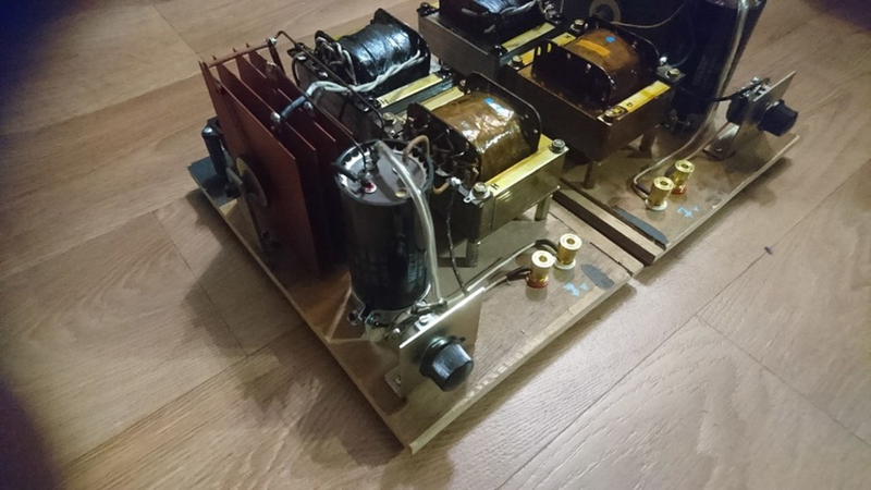
A significant part of the exceptional sound of a truly great FC speaker comes from its power supply. If you neglect this, your speaker will not sound as good as it could, possibly even worse than a similar permanent magnet speaker. The quality of the power supply is critical. You will clearly hear the quality of the tube rectifier or diodes, the internal wiring, the power transformer, and even the material of the chassis. I have tested all these factors, and without attention to these details, an FC speaker will not perform at its best.
For example, if your 555 Western Electric driver doesn’t sound as clear or seems too rough, the issue is likely in the power supply.
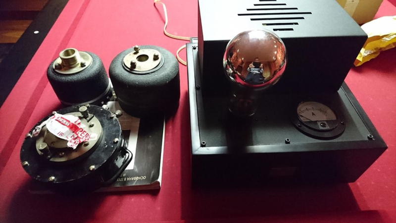
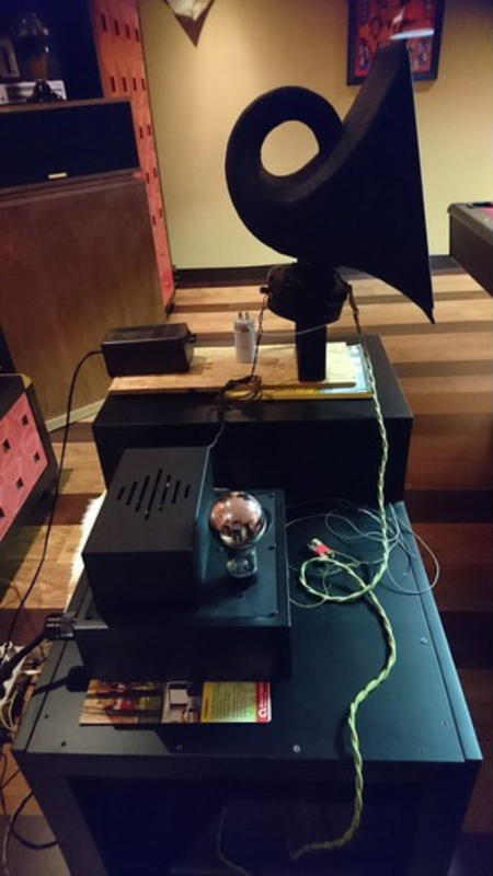
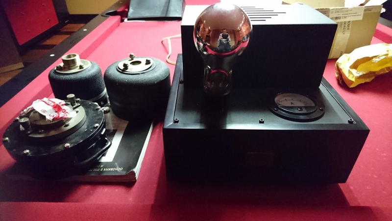
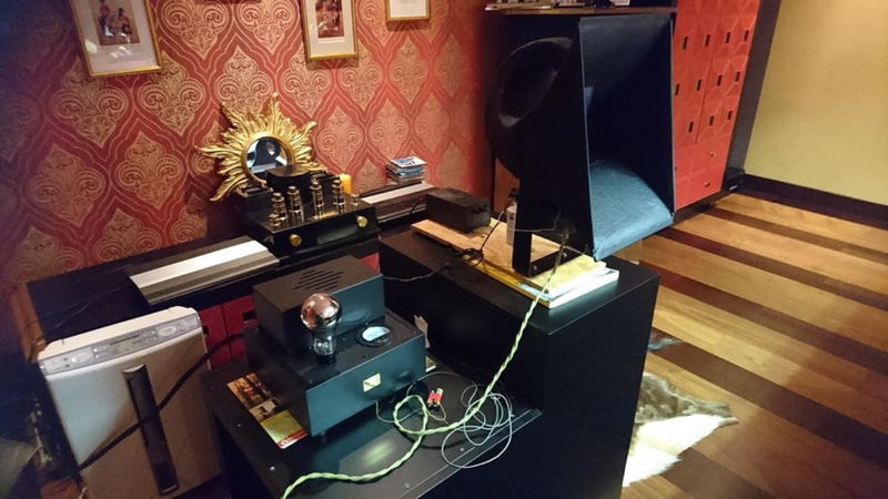
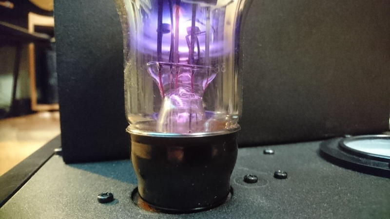
I once completed a similar project and vividly remember the huge difference in sound quality. The power supplies were built using 367 PHILIPS tungars, which provide up to 6 amperes of rectified current. Only after replacing the poor pulse power supply with a tube one it become clear why the 555 cost such a high price. However, while tungars provide great results, they are technically a dead end—difficult to replace and extremely bulky and expensive. On the other hand, silicon or germanium diodes are easier to use, though we get the result that is a more humble in terms of sound quality. Still, good results can be achieved with diodes if the design is done properly.
- Inefficiency and High Operating Costs
Field coil systems are highly inefficient. They require complex power supplies, consume more electricity, and introduce additional consumables like rectifier tubes. This makes them more expensive and less practical compared to permanent magnet designs. - Overheating of the Moving System
Sometimes, the moving system in a field coil speaker overheats, leading to changes in its parameters. This causes the cone to dry out, the coil may become deformed, surround can alter the flexibility like mylar in RADIAN diaphragms that used in JBL drivers. It is essential to not only design a good sounding power supply but also ensure proper cooling for the coil. This is not always an easy task.
Modern manufacturers often use rods instead of a cast housing. This is an effective solution, but only if you’re designing a driver from scratch. When reworking drivers with cast housings, however, creative solutions must be found.
Now, let’s discuss the power supply and the design of the field coil.
I believe the biggest mistake made by modern manufacturers of such drivers is mindlessly copying RCA and Western Electric designs with their 7–15V power supplies. Even if it were 25 volts, like the KINAP 1a13, it wouldn’t change the essence of the matter .
I completely understand the reasoning behind the engineers’ decisions in the 1930s and why they designed it this way:
- Thick wire is faster and easier to wind than 10,000 turns of 0.2mm wire, for example. This makes production cheaper. Additionally, thick wire itself is cheaper to produce because it requires fewer production steps (such as passing through dies to achieve the desired diameter).
- Thick wire is harder to overheat, allowing for a wider range of operating currents. It is safer to work with, especially for untrained personnel.
- Thick wire is more reliable, as it is less likely to short between turns, even when winding without paper. The likelihood of breakage due to internal stress or metal defects is almost nonexistent.
While these points are crucial for professional equipment, they are irrelevant in home audio, where sound quality is the only priority. European manufacturers, such as KLANGFILM, took a different approach. They used high-voltage coils, with the famous Klangfilm 44022 woofer operating at 250V, which allowed the use of a tube rectifier. I believe this approach was the correct one.
Now, I will present my principles for the «ideal power supply» and explain why I believe this approach is the best.
- Field Coil Voltage
If you have the option to choose the winding parameters, the field coil should be designed to provide approximately 200–250V of operating voltage directly from the electrical network (or 100–120V if you live in the USA, although this presents more challenges in terms of using tube rectifiers—lower voltage requires higher current). This allows you to avoid the need for a high-voltage winding, which is crucial for parameters such as clarity and tonal purity. A speaker with a field coil is always very sensitive to the power transformer, and it sounds better when powered not by a classic transformer with a secondary winding, but by an autotransformer. Ideally, the speaker should be powered directly from the electrical network, bypassing transformers entirely. This approach eliminates unpleasant overtones that can make the sound seem clumsy, dirty, granular, and lacking liquidity. - Power Supply and Rectifier Circuit
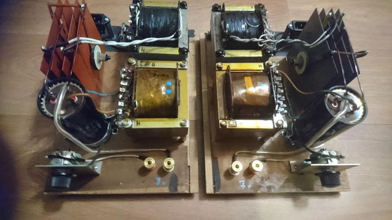
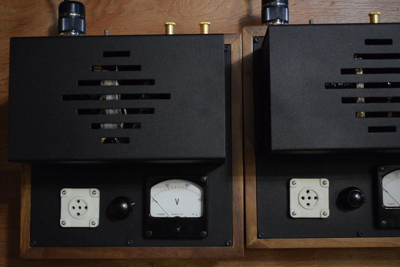
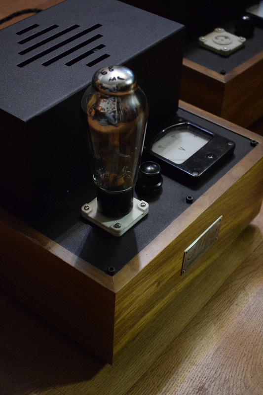
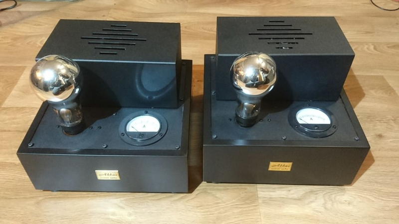
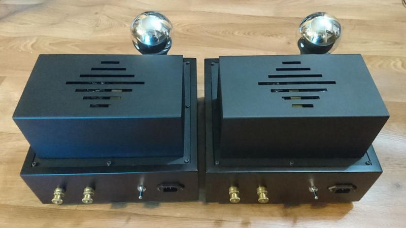
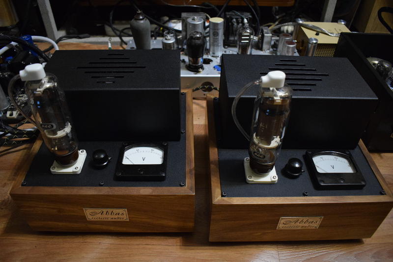
The power supply, or more specifically, the rectifier circuit, should be as simple and short as possible. I prefer so called single phase wave rectifier (SPWR), or briefly half wave rectifier (HWR) which is the oldest method of converting AC voltage to DC voltage using a single tube or a tube with a single plate or a single diode. The half-wave rectifier was popular in the 1900s to the 1920s, and I have been using it for about 20 years since I first learned about it from a man I considered my mentor . Although I later found examples of this rectifier being used in Japanese equipment from the 1970s, it was mainly employed by Japanese DIYers. Tarim Audio also used HWR in one of their tube amplifier designs in the late ’90s.
This is the most musical type of rectifier, despite producing maximum ripple at 50Hz and even increasing the amplitude of this ripple. This means that your tube rectifier should have a current reserve of double or triple the calculated value of DC consumption. However, with high-resistance and high-voltage coils, you can use inexpensive tubes like the 5U4 and still achieve excellent results—sometimes even better than with expensive Tungar tubes. This is also much better than using a 12V power supply with rectification via a cheap Chinese diode bridge.
I am not even talking about using pulse power supplies—this is an extreme case of folly, especially when it comes to such famous drivers as WE555 or WE594. Remember that you will hear the rectifier itself, just as if it were installed in a power amplifier, and possibly even more clearly, given that there is no useful signal in the field coil circuit. This is one of those phenomena that doesn’t have a clear explanation, and if anyone claims they know why it happens, they are lying.
By the way, I have stated many times that I consider the bridge rectifier to be the worst type of rectifier for audio. If the HWR doesn’t suit you, there may be many reasons for this, but you could try using a full-wave rectifier with a center tap on the secondary winding.
The HWR is a great solution in many cases, but it does have limits. It sounds bad if you need to power a high-current stage, consuming around 100–200 mA or more. As result, a power transformer without a gap will operate in core saturation mode, which leads to a poor and gloomy sound.
The half-wave rectifier also has limitations when used in phono RIAA preamplifiers, especially if the rectifier shares a common chassis with the main circuit.
It’s important to note that the magnetic field from the power transformer paired with the HWR irradiates the circuit with huge asymmetrical petals, which affect sensitive valves and signal transformers. In this case, careful shielding of power transformer is necessary, using mu-metal with a thickness of at least 0.5 mm. Proper orientation of the transformers relative to each other is also strongly recommended.
But there are even more exotic ways to use a half-wave rectifier. Did you hear about inverted or underground HWR? I do not think so. There is also a very clever way to get the bias voltage taken from a resistor placed between ground and the center tap. This bias behaves like an automatic bias but sounds more like a fixed one. A similar solution is used in my new preamplifier, the HEPHAESTUS RIAA-line preamplifier. But I will talk about it later. Apologies for digressing slightly.
3. Power Supply Capacitors
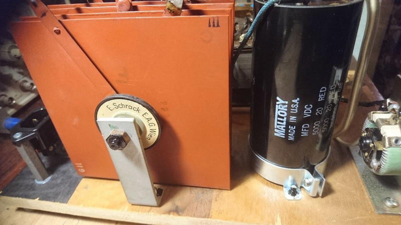
It is advisable to use a single, high-quality capacitor in the power supply, but the tube rectifier imposes restrictions on the value of this capacitor. You can use up to 32 µF with most of tube rectifiers. With selenium or diode rectifiers, the capacitance can be much higher. However, high-quality diodes, whether silicon or germanium, are extremely rare.
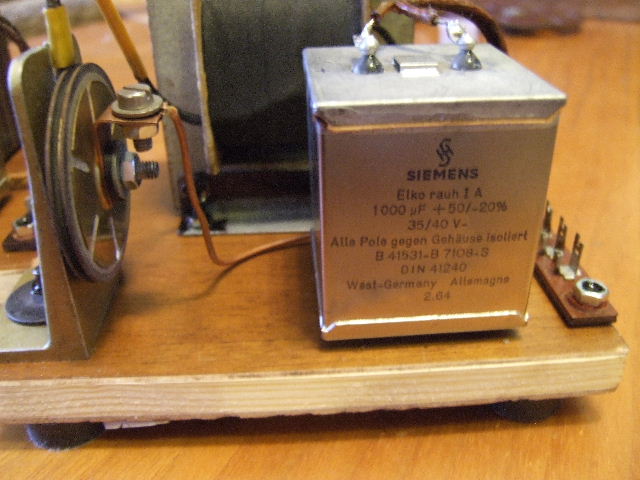
As for the type of capacitor, I prefer German-made PIO (Paper In Oil) capacitors. If higher capacitance can be used, then WKZ, WK, or VK Black Gate capacitors are the best choice.
The number of parts responsible for minimizing ripple should be minimal, but it depends on the inductance of the field coil itself. This is another reason why it’s more advantageous to design the field coil to be high-resistance, high inductance and respectively high-voltage. For instance, the field coil of the Klangfilm 44022 woofer has an inductance of about 100 H. The field coil of a 15-inch Jensen or Magnavox speaker also has about 100 H at 4000–5000 ohms of DC resistance, and around 50 H at 2500 ohms.
This fact makes ripple filtering much easier! With fewer Henrys, you are forced to use an additional choke (or, it is terrible, a solid-state voltage stabilizer). Your speaker will sound much worse, regardless of who made the choke or its construction or used materials. Any additional filtering component distorts and deforms the sound, choking the dynamics—there are no exceptions to this rule. If you want minimal interference from the power supply to the driver’s sound, choose a field coil with maximum inductance and avoid using chokes in the power supply.
Now, I’ll present some considerations that I haven’t heard from anyone else before.
The field coil and voice coil form a transformer. I even measured the ratio of this transformer and looked at its frequency response. Now, just imagine that with a 12-volt supply, you have about 1000 turns in the bias coil, and you create a transformer with a ratio of 1:4 to 1:10. This means that all the noise, ripple and inerference from the power supply can freely penetrate the voice coil. Furthermore, this transformer has a wide frequency range, even though the coils are spaced apart, which complicates the transmission of high frequencies.
Now, let’s consider the coil of the Klangfilm 44022 speaker, which has about 10,000 turns.
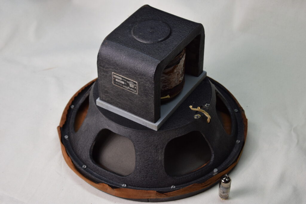
This results in a much narrower-band transformer with a ratio of about 1:100. It is probably unnecessary to say that with such ratios, almost nothing from the power supply will reach the voice coil: noise, hum, HF bursts. If it even does, it will be at negligible levels in the frequency range up to a few hundred Hz.
Finally, the last consideration is the huge inductance, which adds more inertia. What we appreciate so much about field coils—the stability of the magnetic field in the gap—is even more pronounced in a high-voltage, high-resistance, high inductance coil.
If I think of anything else, I’ll add it. That’s all for now. The continuation will come, but in the form of designs.And one more thing—do not listen to the misinformed retellings from pure audio businessmen . They do not understand the depth of the problem, although they sometimes manage to successfully copy other people’s solutions. I have been building power supplies based on a HWR for twenty years. Feel free to ask me if you are interested in more information on this topic.


Please use the Contacts page for inquiries or purchases. Such comments will not be published.